
Monitor connector Pinout
VAXstation (Subd15 pin #) HD Subd15 (pin #)
| VAXstation (Subd15 pin #) | Function | HD Subd15 (pin #) |
|---|---|---|
| 1 | Red High | 1 |
| 10 | Green High | 2 |
| 11 | Blue High | 3 |
| 9 | Red Return | 6 |
| 2 | Green Return | 7 |
| 3 | Blue Return | 8 |
| Hood | Ground | Hood |
Monitor needs to support Sync on Green
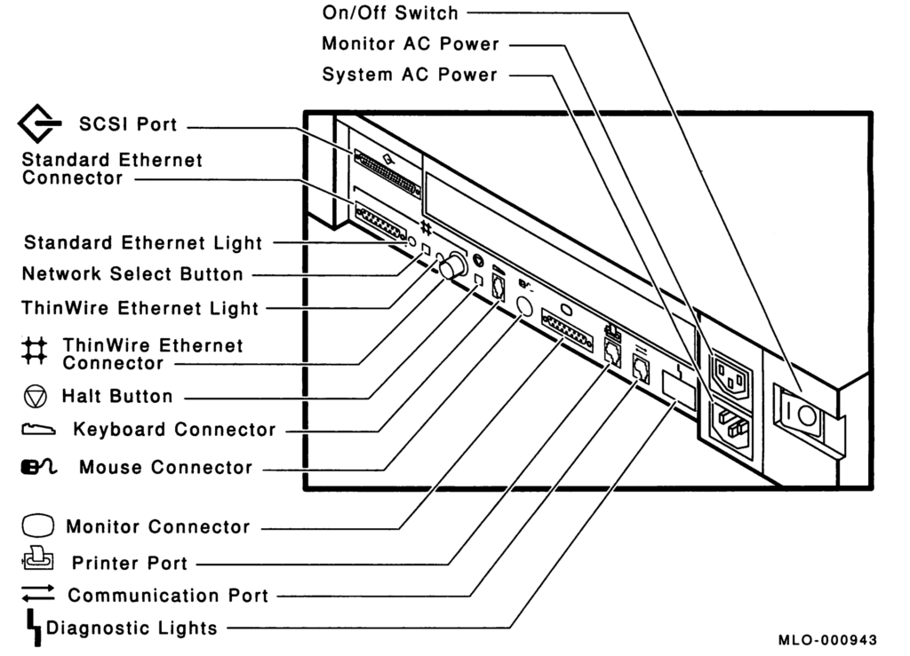
System Unit Ports and Connectors
Diagnostic LED Definitions
There are eight LED’s divided into two felds of four on the back of the system box. These LED’s provide feedback during each phase of power-up initialization and testing. The first four indicate the state of the system while the second four indicate substate and are dependent on the indication given from the state LED’s.
| State | Substate | Definition |
|---|---|---|
| 1111 | 1111 | Power is applies but no instruction is executed. |
| 1111 | 0000 | Power is applied. The ROM code is successfully started and several instructions have been executed. |
| 1110 | 0000 | Console memory sizing routine is entered. Memory to hold the console data structures is located. The substate variables have no meaning in this section of the test. |
| 1101 | 0000 | The console data structures are initialized and have started testing the NVR. |
| 1100 | 0000 | The NVR test completed and the DZ test has started. |
| 1011 | 0000 | The DZ test completes. An optional video has been found but its testing has not been started. This is part of the console determination code. |
| 1011 | 0001 | The DZ test completes. No optional video is installed or, if it is installed, fails self-test. In either case, the base monochrome video test has been entered. |
| 1010 | 0000 | The video subsystem was tested and the console initialization sequence was entered. |
| 1001 | XXXX | The system initializes and power-up testing starts. The substate variable indicates the subsystem test being excuted. See subsystem table below. |
| 1000 | XXXX | The self-test completes with the substate indicating the failing subsystem. See subsystem table below. Enter TEST 50 to see results. |
| 0111 | XXXX | Self-test was entered from the console TEST command. The substate indicats the subsystem test currently being executed. See subsystem table below. Enter TEST 50 to see results. |
| 0110 | XXXX | The self-test completes from the TEST command with the substate indicating the failing subsystem. See subsystem table below. Enter TEST 50 to see results. |
| 0101 | XXXX | The self-test started under control of the APT system. The substate indicats the subsystem test currently being executed. See subsystem table below. Enter TEST 50 to see results. |
| 0100 | XXXX | The system exerciser started from a console TEST command. The substate indicats the value of the lower four bits of the command. If the system exerciser starts with a T 101, the substate contains a 0x0001. Read the test results on the screen. |
| 0011 | 0000 | The system exerciser started under control of the APT test delivery system. Read the test results on the screen. |
| 0010 | XXXX | The entity-based module received a request from a host to enter monitor mode. This lets the host send commands to the system. This is indicated if the functionality of the EBM is implemented at a later release of the system ROM. Reserved for future use. |
| 0001 | XXXX | Console mode was successfully entered and is ready to accept commands. This does not apply to power on. The substate indicates the failing subsystem if there is one. This differs from a self-test complete, because the console can be entered by means other than TEST command or power-on halt (for example HALT button). |
| 0000 | XXXX | Attempting to boot the system. Once control passes to VMB, the state LED’s have no meaning. |
| Subsystem Table | |||
|---|---|---|---|
| Substate | Subsystem | Substate | Subsystem |
| 1111 | MONO | 1110 | CLK |
| 1101 | NVR | 1100 | DZ |
| 1011 | MEM | 1010 | MM |
| 1001 | FP | 1000 | IT |
| 0111 | STRG-1 or SCSI-A | 0110 | SCSI-A or SCSI-B |
| 0101 | SYS | 0100 | 8PLN |
| 0011 | (option) | 0010 | (option) |
| 0001 | NI | ||
Leave a Reply